
Two medium-voltage vacuum circuit breakers can have the same primary voltage and current ratings but require different secondary wiring. For an OEM panel, a retrofit or a remote-control project, the control circuit should be specified before the breaker is ordered—not discovered during commissioning.
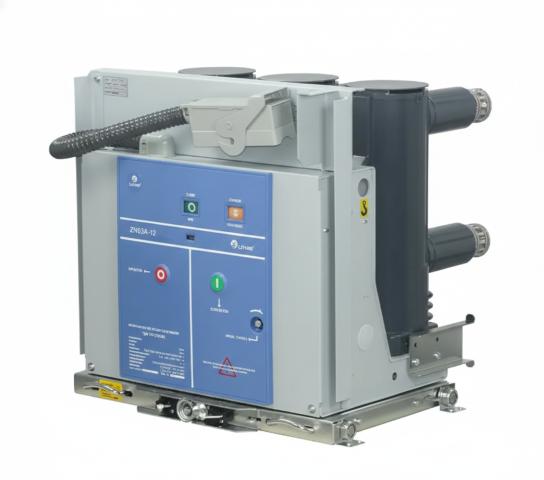
What the three main control devices do
The spring-charging motor stores mechanical energy in the closing spring. Depending on the design, manual charging may also be possible. The motor supply and charging indication must match the project’s auxiliary power system.
The closing coil releases the charged spring when a valid close command is given and the required permissives are satisfied. A close signal alone should not be assumed to close the breaker: spring state, breaker position and interlocking logic also matter.
The trip coil operates the opening mechanism when a valid trip signal is received. A protection relay may initiate the signal, but the supply voltage, wiring and any trip-circuit monitoring requirement must be agreed for the actual panel design.
These functions are related but are not interchangeable. Do not assume that the motor, closing coil and trip coil use the same voltage or that every accessory is included with a standard breaker quotation.
Confirm the auxiliary supply before comparing quotations
An RFQ should list the available AC and/or DC auxiliary supplies and state which supply serves each function. Ask the supplier to confirm the permitted voltage range and the current or power demand from the selected model’s drawings and datasheet. This is particularly important when a replacement breaker must connect to an existing panel or control cabinet.
| RFQ item | Information to provide or confirm |
|---|---|
| Spring-charging motor | Required supply type and voltage; manual-charging requirement; charging indication |
| Closing coil | Supply type and voltage; local/remote close commands; close permissives |
| Trip coil | Supply type and voltage; protection and manual trip commands; second trip coil if required |
| Auxiliary contacts | Number and contact states needed for indication, interlocking and remote monitoring |
| Secondary connection | Plug or terminal arrangement, pin assignment and existing-panel compatibility |
| Control documents | Approved schematic, terminal diagram, accessory list and operating sequence |
This table is a procurement checklist, not a wiring diagram. The manufacturer’s model-specific documentation and the project’s protection design govern the final circuit.
Auxiliary contacts and interlocks
Auxiliary contacts report breaker state to the protection, indication and supervisory systems. Many control schemes use contacts that change state when the breaker opens or closes, but the required quantity, terminal numbers and contact ratings must be checked against the chosen breaker. For a withdrawable arrangement, position contacts and the secondary plug may add further signals.
Specify the interlocking sequence instead of simply writing “standard interlocks.” The switchgear builder should confirm when closing is permitted in service or test position, how the earthing switch and doors are interlocked, and which signals must be available to SCADA or a remote terminal unit. Anti-pumping requirements should also be included where the project control philosophy calls for them. These details must be reviewed as a complete panel scheme, not inferred from the breaker rating.
Three common RFQ gaps
- Only the primary ratings are supplied. Voltage, current and short-circuit ratings do not define the secondary control package.
- “Remote control” is requested without an I/O list. The supplier cannot confirm the necessary contacts, coils, indicators or communication interface without the desired signals and operating sequence.
- A replacement breaker is selected without the existing schematic. A physically similar unit may still have a different secondary plug, terminal assignment or interlock logic.
For retrofit work, provide the existing breaker nameplate, panel drawings, control schematic, secondary connector details and clear photographs. For new panels, send the single-line diagram and the protection/control specification.
What to request from the supplier
Before releasing an order, request a model-specific accessory list, control schematic, terminal assignment, outline drawing and operation/maintenance documentation. Compare those documents with the panel designer’s approved scheme. If factory acceptance testing is planned, agree which opening, closing, charging, indication and interlock functions will be demonstrated; do not assume the same test scope applies to every project.
Enertro’s VS1 / ZN63A-12 vacuum circuit breaker is one product family to review for indoor medium-voltage switchgear. Its exact mechanism and secondary accessories require written model-and-project confirmation. For broader selection criteria, read the vacuum switchgear selection guide.
To request a technical quotation, send the electrical ratings, available auxiliary supplies, breaker arrangement, required control signals and drawings through the Enertro contact page. Enertro can then confirm the proposed configuration rather than guessing from the voltage class alone.